- +91-11-9810681132, 9868532156
- info@mittalenterprises.com
Note: No part of this website may be reproduced, stored in a retrieval, or transmitted in any form or by any mean
Note: No part of this website may be reproduced, stored in a retrieval, or transmitted in any form or by any mean


Objective: Determination of Energy Band Gap of Silicon, Germanium etc using diodes and light emitting diodes.

|
|||
|
B-H Curve Unit B-H Curve Unit INSTRUMENT It Consists of Electronic Circuity housed in a cabinet. One specimen of transformer stamping and another sample of ferrite ring is also supplied. This complete unit requires a C.R.O. to perform the experiment. The Unit enables one to trace the B-H loop (hysteresis) of a ferromagnetic specimen using a cathode ray oscilloscope. A measurement of the area of the loop leads to the evaluation of energy loss in the specimen The experimental arrangement is shown in Fig.1
|
|||
| Enquiry | |||

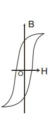 One of the specimens used in the unit is made using transformer stampings.There are two windings on the specimen (primary and secondary). The primary is fed to low A.C. voltage (50 Hz). This produces a magnetic field H in the specimen. The voltage across R1 (resistance connected in series with the primary) is proportional to the magnetic field. It is given to the horizontal input of the CRO. The A.C. magnetic field induces a voltage in the secondary coil. The voltage induced is proportional to dB/dT (B-flux density). This voltage is applied to a passive integrating circuit. The output of the integrator is proportional to B and fed to the vertical input of the CRO. As a result of the application of a voltage proportional to H to the Horizontal (input axis and a voltage proportional to B to the vertical (input) axis, the loop shown in fig. 2 is formed. The transformer Fig.3